Tuesday, September 4, 2018

servo motor with arduino

     Servo Motor

A Servo Motor is a small device that has an output shaft. This shaft can be positioned to specific angular positions. As long as the coded signal exists on the input line, the servo will maintain the angular position of the shaft. If the coded signal changes, the angular position of the shaft changes. In practice, servos were used in radio-controlled airplanes to position control surfaces like the elevators and rudders. They are also used in radio-controlled cars, puppets, and of course, robots.

Hardware Required


  • 1 x  servo motor
  • 1 x Arduino uno
  • 3 x jumper wire


Wiring Diagram
The best thing about a servo motor is that it can be connected directly to an Arduino.
  • Servo red wire – 5V pin Arduino         
  • Servo brown wire – Ground pin Arduino         
  • Servo yellow wire – 9 pin Arduino


connection with ardunio-


code-


#include //Servo library Servo servo_test; //initialize a servo object for the connected servo int angle = 0; void setup() { servo_test.attach(9); // attach the signal pin of servo to pin9 of arduino } void loop() { for(angle = 0; angle < 180; angle += 1) // command to move from 0 degrees to 180 degrees { servo_test.write(angle); //command to rotate the servo to the specified angle delay(15); } delay(1000); for(angle = 180; angle>=1; angle-=5) // command to move from 180 degrees to 0 degrees { servo_test.write(angle); //command to rotate the servo to the specified angle delay(5); } delay(1000); }
Servo servo_test; //initialize a servo object for the connected servo int angle = 0; void setup() { servo_test.attach(9); // attach the signal pin of servo to pin9 of arduino} void loop() { for(angle = 0; angle < 180; angle += 1) // command to move from 0 degrees to 180 degrees { servo_test.write(angle); //command to rotate the servo to the specified angle delay(15); } delay(1000); for(angle = 180; angle>=1; angle-=5) // command to move from 180 degrees to 0 degrees { servo_test.write(angle); //command to rotate the servo to the specified angle delay(5); } delay(1000);}

DC motor with arduno

    DC Motor

DC Motor

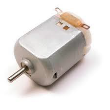
 A DC motor (Direct Current motor) DC motors generally have just two leads, one positive and one negative. If you connect this two leads directly to a battery, the motor will rotate. If you switch on, the motor will rotate in the opposite direction.


Warning − Do not drive the motor directly from Arduino board pins. This may damage the board. Use a driver Circuit or an IC.
- we can use relay instead of motor IC
We will divide this chapter into three parts −
  • Just make your motor spin
  • Control motor speed
  • Control the direction of the spin of DC motor
Components Required
You will need the following components −
  • 1x Arduino UNO r3
  • 1x PN2222 Transistor
  • 1x Small 6V DC Motor
  • 1x 1N4001 diode
  • 1x 270 Ω Resistor

motor connections with arduino -


code-

const int pwm = 2 ; //initializing pin 2 as pwmconst int in_1 = 8 ;const int in_2 = 9 ; //For providing logic to L298 IC to choose the direction of the DC motor void setup(){pinMode(pwm,OUTPUT) ; //we have to set PWM pin as outputpinMode(in_1,OUTPUT) ; //Logic pins are also set as outputpinMode(in_2,OUTPUT) ;} void loop(){//For Clock wise motion , in_1 = High , in_2 = Low digitalWrite(in_1,HIGH) ;digitalWrite(in_2,LOW) ;analogWrite(pwm,255) ; /*setting pwm of the motor to 255we can change the speed of rotaionby chaning pwm input but we are onlyusing arduino so we are using higestvalue to driver the motor */ //Clockwise for 3 secsdelay(3000) ; //For brakedigitalWrite(in_1,HIGH) ;digitalWrite(in_2,HIGH) ;delay(1000) ; //For Anti Clock-wise motion - IN_1 = LOW , IN_2 = HIGHdigitalWrite(in_1,LOW) ;digitalWrite(in_2,HIGH) ;delay(3000) ; //For brakedigitalWrite(in_1,HIGH) ;digitalWrite(in_2,HIGH) ;delay(1000) ; }

Temperature Sensor with arduino in iot

Temperature Sensor -


The Temperature Sensor LM35 series are precision integrated-circuit temperature devices with an output voltage linearly proportional to the Centigrade temperature.
The LM35 device has an advantage over linear temperature sensors calibrated in Kelvin, as the user is not required to subtract a large constant voltage from the output to obtain convenient Centigrade scaling. The LM35 device does not require any external calibration or trimming to provide typical accuracies of ±¼°C at room temperature and ±¾°C over a full −55°C to 150°C temperature range.

Temperature Sensor connection with arduino-


technical specification

  • celsius temperature
  • Linear + 10-mV/°C scale factor
  • 0.5°C ensured accuracy (at 25°C)
  • Rated for full −55°C to 150°C range
  • Suitable for remote applications

Components Required

You will need the following components −
  • 1 × Breadboard
  • 1 × Arduino Uno R3
  • 1 × LM35 sensor

 code -


// We'll use analog input 0 to measure the temperature sensor's
// signal pin.
const int temperaturePin = 0;
void setup()
{
    Serial.begin(9600); 
}
void loop()
{
   Serial.print("voltage: ");
  Serial.print(voltage); 
 Serial.print("  deg C: ");  
Serial.print(degreesC);  
Serial.print("  deg F: ");
  Serial.println(degreesF); 
   delay(1000);
 // repeat once per second (change as you wish!)
}
float getVoltage(int pin)
{
  return (analogRead(pin) * 0.004882814);
 }


water sensor with arduino

  Water Sensor


Water sensor is designed for water detection, which can be widely used in sensing rainfall, water level, and even liquid leakage.


Connecting a water sensor to an Arduino is a great way to detect a leak, spill, flood, rain, etc. It can be used to detect the presence, the level, the volume and/or the absence of water. While this could be used to remind you to water your plants, there is a better Grove sensor for that. The sensor has an array of exposed traces, which read LOW when water is detected.
In this chapter, we will connect the water sensor to Digital Pin 8 on Arduino, and will enlist the very handy LED to help identify when the water sensor comes into contact with a source of water.

Components Required

You will need the following components −
  • 1 × Breadboard
  • 1 × Arduino Uno R3
  • 1 × Water Sensor
  • 1 × led
  • 1 × 330 ohm resistor
water sensor connection with arduino -


code for water level sensor -


/* Arduino Tutorial - Watel Level Sensor 40mm
   More info: */

const int read = A0; //Sensor AO pin to Arduino pin A0
int value;       //Variable to store the incomming data

void setup()
{
//Begin serial communication
Serial.begin(9600);
}

void loop()
{
value = analogRead(read); //Read data from analog pin and store it to value variable
if (value<=480){ 
Serial.println("Water level: 0mm - Empty!"); 
}
else if (value>480 && value<=530){ 
Serial.println("Water level: 0mm to 5mm"); 
}
else if (value>530 && value<=615){ 
Serial.println("Water level: 5mm to 10mm"); 
}
else if (value>615 && value<=660){ 
Serial.println("Water level: 10mm to 15mm"); 
}
else if (value>660 && value<=680){ 
Serial.println("Water level: 15mm to 20mm"); 
}
else if (value>680 && value<=690){ 
Serial.println("Water level: 20mm to 25mm"); 
}
else if (value>690 && value<=700){ 
Serial.println("Water level: 25mm to 30mm"); 
}
else if (value>700 && value<=705){ 
Serial.println("Water level: 30mm to 35mm"); 
}
else if (value>705){ 
Serial.println("Water level: 35mm to 40mm"); 
}
delay(5000); // Check for new value every 5 sec
}


Ultrasonic Sensor

Ultrasonic Sensor  


The HC-SR04 ultrasonic is sensor used to determine the distance of an object . It offers excellent non-contact range detection with high accuracy and stable readings in an easy-to-use package from 2 cm to 400 cm or 1” to 13 feet.
The operation is not affected by sunlight or black material, although acoustically, soft materials like cloth can be difficult to detect. It comes complete with ultrasonic transmitter and receiver module.


connections with arduino-


Technical Specifications

  • Power Supply − +5V 
  • Ranging Distance − 2cm – 400 cm/1″ – 13ft
  • You will need the following components −
  • 1 × Breadboard
  • 1 × Arduino Uno R3
  • 1 × ULTRASONIC Sensor

code to find the distance of object before ultrasonic sensor -

const int trigPin = 12;
// #define trigpin 12;
const int echoPin = 11;
long microsecondsToCentimeters(long microseconds)
{
  
  return microseconds / 29 / 2;
}
long microsecondsToInches(long microseconds)
{
  
  return microseconds / 75 / 2;
}
void setup()
{
  Serial.begin(9600);
  }
  void loop()
  {
    long duration,inches ,cm;
   pinMode(trigPin, OUTPUT);
  digitalWrite(trigPin, LOW);
  delayMicroseconds(2);
  digitalWrite(trigPin, HIGH);
  delayMicroseconds(10);
  digitalWrite(trigPin, LOW);

  // Read the signal from the sensor: a HIGH pulse whose
  // duration is the time (in microseconds) from the sending
  // of the ping to the reception of its echo off of an object.
  pinMode(echoPin, INPUT);
  duration = pulseIn(echoPin, HIGH);

  // convert the time into a distance

  cm = microsecondsToCentimeters(duration);
  
  Serial.print(cm);
  Serial.print("cm");
  Serial.print("            ");
  inches = microsecondsToInches(duration);
  
  Serial.print(inches);
  Serial.print("inches");
  Serial.println();
 }